Floor Heating Control
It is possible to define a control of the heat emission in a thermal zone as a floor heating system, or rather a construction heating system. This means that the power from a heat emitting system can be placed on one of the constructions of the thermal zone.
As the control for this kind of floor heating systems is directly connected to the face in which the heat is delivered, it is necessary to define a new floor heating control for each thermal zone with this kind of floor heating. It is thus not, as in other BSim controls, possible to use the same control in more than one thermal zone.
Floor heating is defined in the same way as an ordinary radiator in a thermal zone, and thus replaces it for a certain time definition. It is not possible to have both a radiator and a floor heating system in a thermal zone at the same time.
A floor heating system is defined by the installed power (given on the Heating tab) and a control strategy at the FloorHeatCtrl tab. It is also possible to give a negative value of Max Power and Min. Power and thus simulate cooling inside the constructions.
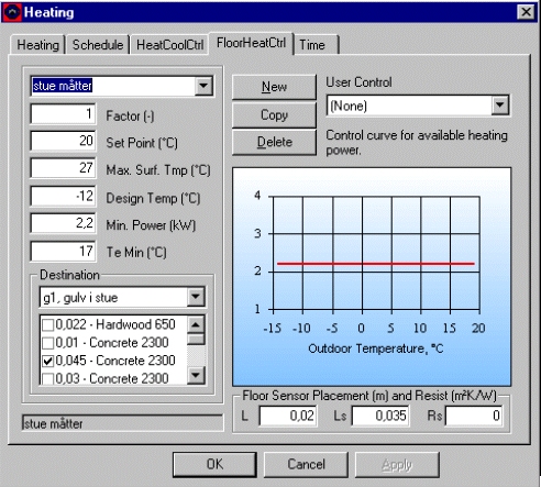
The control of the floor heating system is defined by the following parameters:
Factor: Defines what fraction (0-1) of the installed power (defined at the Heating tab) is available for the actual floor heating system.
Set Point: Is the operative temperature that will be attempted to maintain in the thermal zone where the floor heating system is defined.
Max Surf. Temp: Is the upper limit of the surface temperature in the construction where the power of the floor heating system is given. If the surface temperature goes beyond the Max Surf. Temp. the heat emission will be zero.
Design Temp: Is the ambient temperature below which the floor heating system has its maximum power (= Factor MaxPower - from the Heating* tab) available.
Min. Power: Is the minimum power that can be emitted from the system. If a power requirement is calculated to be below Min. Power, the system is terminated. Between Factor and MaxPower the control of the system is defined according to the line in the graph of the dialog.
Te Min: Is the ambient temperature above which the floor heating system is terminated. Te Min. creates, together with Min. Power the bend at the rightmost of the control curve.
Destination: In this selection box, the construction to receive the power of the floor heating system have to be picked. It is important to give sensible names to the constructions in order to pick the right construction for the construction heating system. Right click on the construction name in the tree structure to change the name of the construction.
When a construction is selected the material layers (counted from the inside the actual thermal zone) of the construction is shown. Each layer is shown with its thickness (m) and material name. In the tick-box at the left side of the layers indicates where the power is to be given to the construction. The power will enter the model between the selected layer and the previous layer. The division into material layers must thus be made so it is possible to place the power in the correct location. It is thus not possible to select the first layer as destination for the floor heating.
The power emitted by the floor heating system is shown in the results log as qHeat for the construction if saving results from Constructions are turned on at the tsbi5 + Options tab.Floor Sensor Placement: The heat emission is assumed to be given in a network of parallel heat sources (pipes or electrical wires), and a temperature sensor is located in the same layer as the heat source. There will thus be a time delay of the sensor temperature compared to the layer where the heat is emitted. The distance between the individual heat sources is given as L (m), and the distance from a heat source to the sensor as Ls (m). Finally an additional resistance (Resist, m2K/W) for the heat transfer between the construction and the sensor can be given.
User Control: It is possible to define individual control functions, which can be selected from the list of User Controls. A user-defined control can be installed on the PC as a plug-in, and thus does not require a recompilation of BSim. A control function must be programmed in C++ and follow some given rules. If None is selected, the built-in control function will be used.
When clicking the Use This button, the defined control of the floor heating system is transferred to the Schedule tab. If the current tab is left without clicking the Use This button, any changes are not registered on the Schedule tab.
Using the New button it is possible to create new control strategies for floor heating systems, i.e. for different periods of the year or in different thermal zones.
The Copy button is used for creating a copy of the current control strategy. If a control strategy used elsewhere has to be changed, it is necessary to create a copy and edit that copy. If a copy is not created, the changes will affect any item where the actual control strategy is used in the entire model.
The Delete-button deletes the current control strategy.